Comment mettre en place EtherChannel (LACP) pour améliorer les performances réseau
- Mise à jour le 28 avril 2025
Nous allons voir ici comment améliorer les performances de son réseau avec la technologie EtherChannel couplée avec le protocole de négociation Link Aggregation Control Protocol (LACP).
Pour information et d'après l'article Wikipedia : https://fr.wikipedia.org/, EtherChannel est une technologie d'agrégation de liens. Grâce à cette fonctionnalité nous pouvons utiliser jusqu'à 8 ports actifs pour une bande passante totale de 800 Mbit/s, 8 Gbit/s ou 80 Gbit/s selon la vitesse des ports configurés.
- Les principales propriétés du protocole LACP sont :
- standard IEEE Ethernet
- Tolérance aux pannes (failover) automatique
- Configuration dynamique
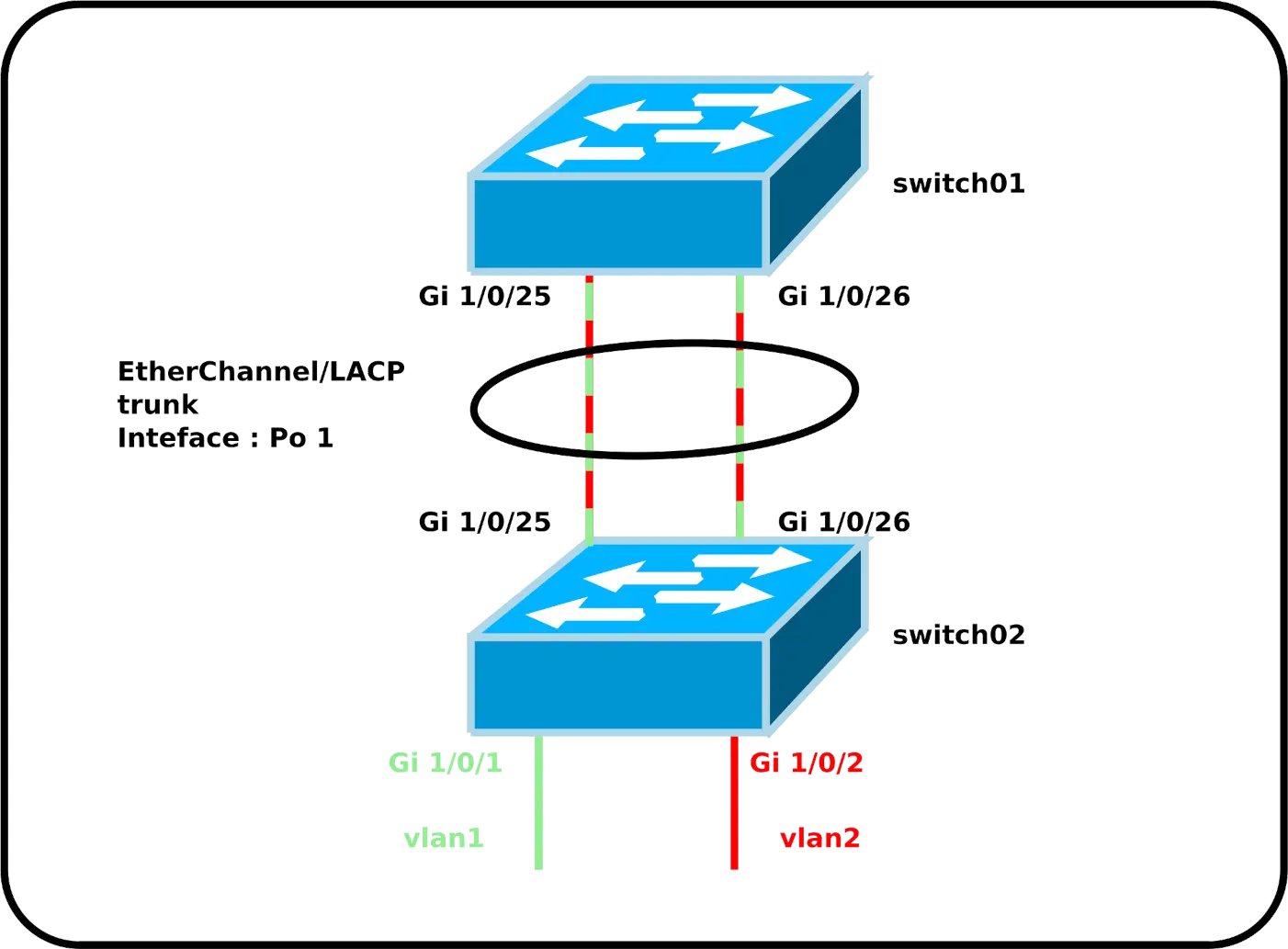
EtherChannel entre deux commutateurs
Configuration
Commençons avec une configuration simple où l'on a deux vlan (1 et 2 pour rester simple) et un lien trunk entre nos commutateurs. Dans le but d'améliorer la bande passante entre eux, nous allons créer un lien EtherChannel sur l'interface trunk et qui sera ici composée de deux liens Gigabit.
- Configuration du switch01 :
switch01(config)# interface range GigabitEthernet1/0/25-26
switch01(config-if-range)# switchport mode trunk
switch01(config-if-range)# switchport trunk allowed none
switch01(config-if-range)# switchport trunk allowed vlan 1,2
switch01(config-if-range)# channel-protocol lacp
switch01(config-if-range)# channel-group 1 mode passive- Configuration du switch02 :
switch02(config)# interface range GigabitEthernet1/0/25-26
switch02(config-if-range)# switchport mode trunk
switch01(config-if-range)# switchport trunk allowed none
switch02(config-if-range)# switchport trunk allowed vlan 1,2
switch02(config-if-range)# channel-protocol lacp
switch02(config-if-range)# channel-group 1 mode active- Nous pouvons maintenant configurer notre interface EtherChannel comme n'importe quelle autre interface en utilisant le nom
Po 1:
switch02(config)# interface port-channel 1Vérification de la configuration
- Vérifier l'état de nos liens EtherChannel :
switch01# show etherchannel summary
Flags:  D - down        P - bundled in port-channel
        I - stand-alone s - suspended
        H - Hot-standby (LACP only)
        R - Layer3      S - Layer2
        U - in use      N - not in use, no aggregation
        f - failed to allocate aggregator

        M - not in use, minimum links not met
        m - not in use, port not aggregated due to minimum links not met
        u - unsuitable for bundling
        w - waiting to be aggregated
        d - default port

        A - formed by Auto LAG


Number of channel-groups in use: 1
Number of aggregators:           1

Group  Port-channel  Protocol    Ports
------+-------------+-----------+-----------------------------------------------
1 Po1(SU) LACP Gi1/0/25(P) Gi1/0/26(P)- Vérifier la méthode de load-balancing utilisée :
switch01# show etherchannel load-balance
EtherChannel Load-Balancing Configuration:
        src-dst-ip

EtherChannel Load-Balancing Addresses Used Per-Protocol:
Non-IP: Source XOR Destination MAC address
  IPv4: Source XOR Destination IP address
IPv6: Source XOR Destination IP address- Vérifier le fonctionnement de la répartition de charge :
switch01# show etherchannel port-channelAutre
- Configurer la méthode de répartition de charge :
switch01(config)# port-channel load-balance src-dst-portEtherChannel sur un Serveur Windows

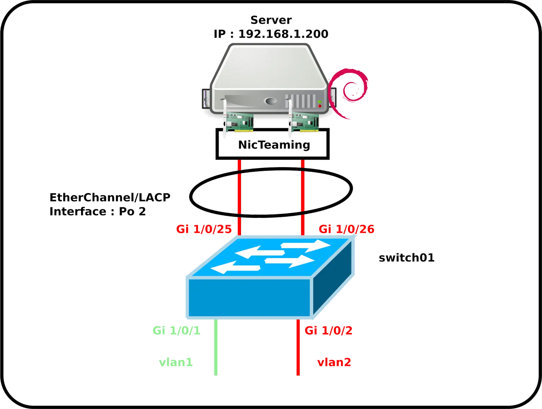
EtherChannel peut aussi être configuré sur les Serveurs Windows. Nous verrons ici un exemple d'un serveur avec deux interfaces réseau.
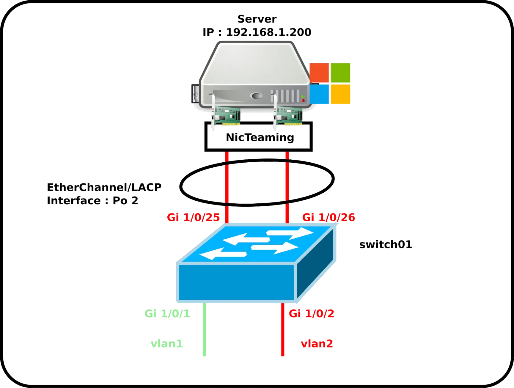
Configuration du commutateur Cisco
- Configurer le switch01 :
switch01(config)# interface range GigabitEthernet1/0/25-26
switch01(config-if)# switchport mode access
switch01(config-if)# switchport access vlan 2
switch01(config-if)# channel-protocol lacp
switch01(config-if)# channel-group 2 mode passive- Nous pouvons maintenant configurer notre interface EtherChannel comme n'importe quelle autre interface en utilisant le nom
Po 2:
switch01(config)# interface port-channel 2Configuration du serveur Windows
Configuration avec l'interface graphique
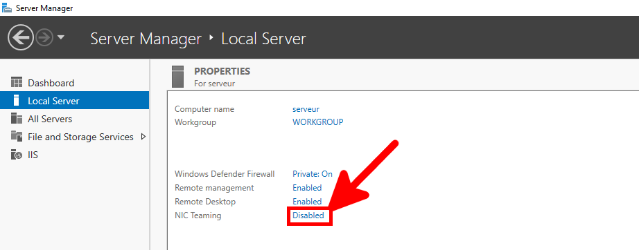
- Depuis le Gestionnaire de serveur, cliquer sur le lien Association de carte réseau :
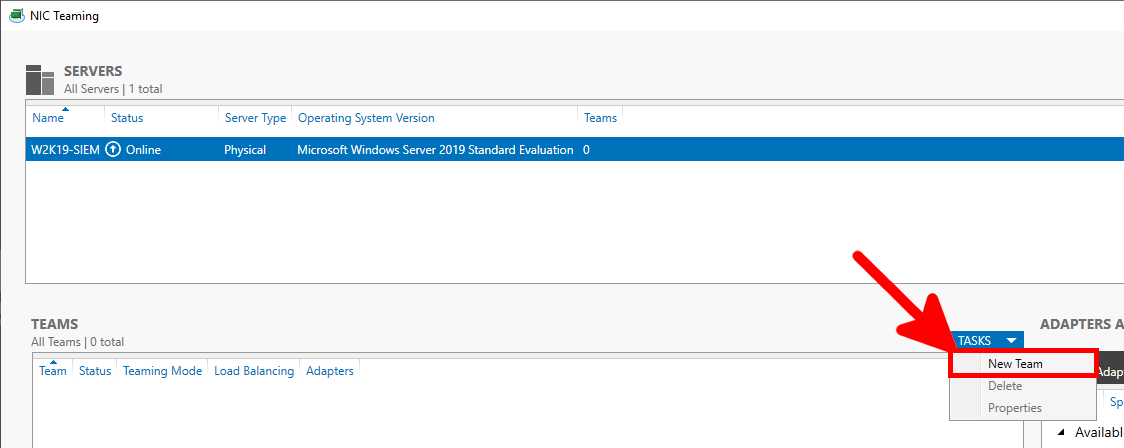
- Depuis la fenêtre d'Association de carte réseau, créer une nouvelle équipe :
- Donner un nom, paramétrer le mode d'équipe sur LACP et le mode d'équilibrage de charge sur Address Hash :
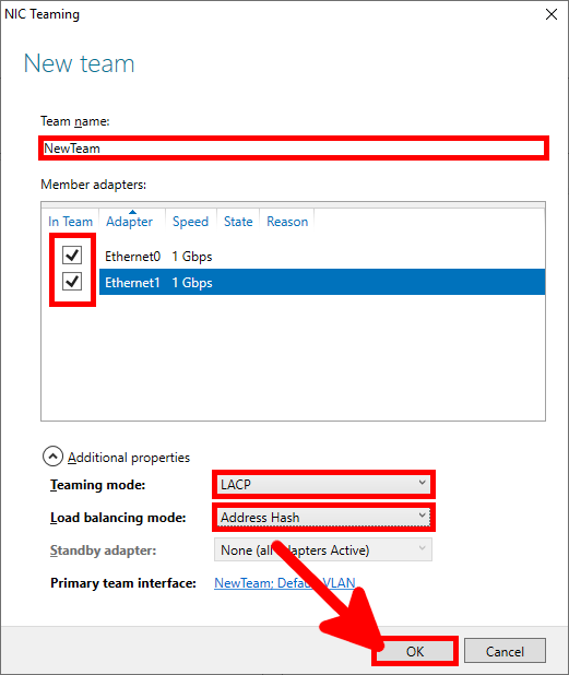
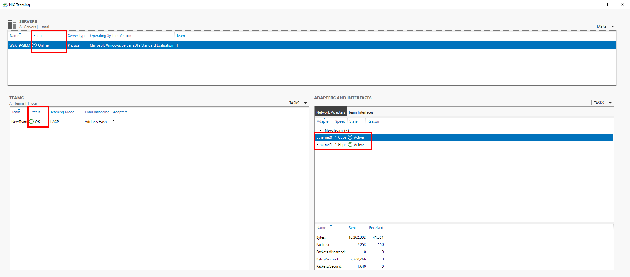
- Vérifier que tout est OK :
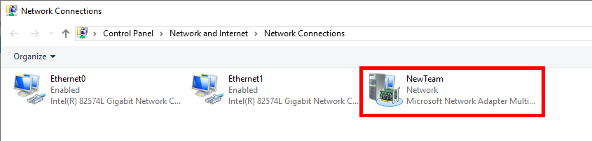
- Depuis le Gestionnaire de connexions réseau, configurer la «Team Interface» comme n'importe qu'elle interface réseau :
PowerShell
- On pourra faire la même chose avec une seule ligne PowerShell :
PS C:\ > New-NetLBFOTeam -LoadBalancingAlgorithm IPAddresses -TeamingMode Lacp -Name NewTeam -TeamMembers Ethernet0,Ethernet1 -Confirm:$falseEtherChannel sur un Serveur GNU/Linux

Configuration du commutateur Cisco
- Configuration du switch01 :
switch01(config)# interface range GigabitEthernet1/0/25-26
switch01(config-if)# switchport mode access
switch01(config-if)# switchport access vlan 2
switch01(config-if)# channel-protocol lacp
switch01(config-if)# channel-group 2 mode active- Nous pouvons maintenant configurer notre interface EtherChannel comme n'importe quelle autre interface en utilisant le nom
Po 2:
switch01(config)# interface port-channel 2Configuration du serveur Debian
- Installer le paquet ifenslave, nécessaire pour activer l'agrégation de liens :
root@host:~# apt-get install ifenslave- Éditer le fichier
/etc/network/interfaces, et créer l'interfacebond0. Ici avec les interfaces physiqueseth0eteth1:
# This file describes the network interfaces available on your system
# and how to activate them. For more information, see interfaces(5).

source /etc/network/interfaces.d/*

# The loopback network interface
auto lo
iface lo inet loopback

auto bond0
iface bond0 inet static
    address 192.168.1.200
    netmask 255.255.255.0
    network 192.168.1.0
    gateway 192.168.1.254
    bond-slaves eth0 eth1
    #4 for LACP/802.3ad
    bond-mode 4
    #frequency of link status check in milliseconds
    bond-miimon 100
    bond-downdelay 200
    bond-updelay 200
    bond-lacp-rate fast
    #mac and ip
bond-xmit-hash-policy layer2+3- Redémarrer le serveur Debian :
root@host:~# reboot- Vérifier que l'interface
bond0soit active :
root@host:~# ip address show dev bond0
4: bond0: <BROADCAST,MULTICAST,MASTER,UP,LOWER_UP> mtu 1500 qdisc noqueue state UP group default qlen 1000
    link/ether 72:17:b9:8d:1e:ad brd ff:ff:ff:ff:ff:ff
    inet 192.168.1.200/24 brd 192.168.1.255 scope global bond0
       valid_lft forever preferred_lft forever
    inet6 fe80::7017:b9ff:fe8d:1ead/64 scope link
valid_lft forever preferred_lft forever- Afficher les informations EtherChannel de l'interface
bond0:
root@host:~# cat /proc/net/bonding/bond0
Ethernet Channel Bonding Driver: v5.10.0-9-amd64

Bonding Mode: IEEE 802.3ad Dynamic link aggregation
Transmit Hash Policy: layer2+3 (2)
II Status: up
II Polling Interval (ms): 100
Up Delay (ms): 200
Down Delay (ms): 200
Peer Notification Delay (ms): 0

802.3ad info
LACP rate: fast
in links: 0
Aggregator selection policy (ad_select): stable
System priority: 65535
System MAC address: 72:17:b9:8d:1e:ad
Active Aggregator Info:
        Aggregator ID: 1
        Number of ports: 1
        Actor Key: 15
        Partner Key: 1
        Partner Mac Address: 00:00:00:00:00:00
root@host:~# cat /sys/class/net/bond0/bonding/mode
802.3ad 4